
Mapping and Localization from Planar Markers
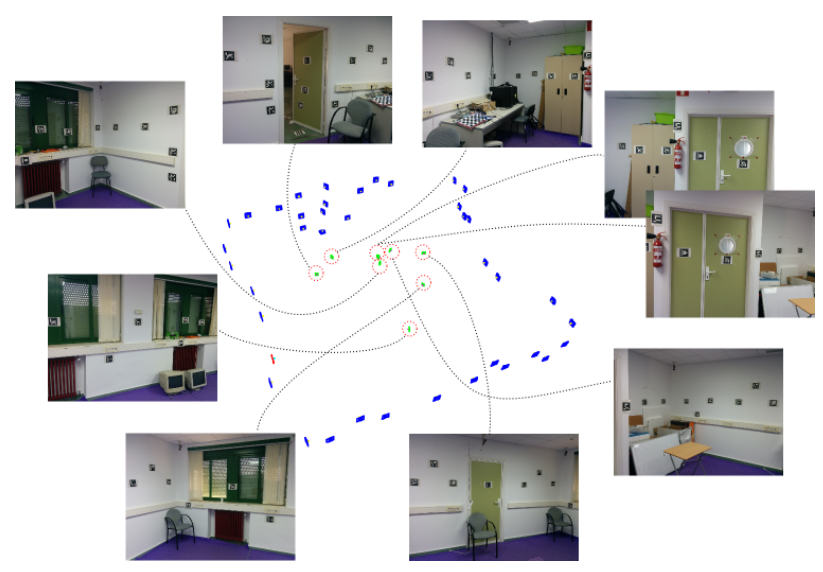
This project allows the creation of cost-effective camera localization systems based on squared planar markers you can print at home. The map shown above has been created using these nine images.
Print the markers, place them in the environment and record a video or take pictures of them (see image above). This project analyzes the images and returns the 3D location of the markers: the marker map. The map generated can be used by ArUCO library for localizing your camera.
Code and Windows Binaries of usage can be obtained at sourceforge.
A technical description can be obtained here.
INSTALATION
Download from sourceforge
Linux:
cd path; mkdir build;cd build;cmake ..;make ;make install;
Windows:
Use QtCreator if you have never use cmake. Open the project with it, and compile. You must indicate the option -DOpenCV_DIR where you have OpenCv installed.
HOW TO USE
Use the aruco library to create a set of markers. Download aruco, http://www.uco.es/investiga/grupos/ava/node/26
compile and then, and use utils/aruco_print_marker or utils/aruco_print_dictionary programs.
Take your camera and calibrate it. You can calibrate either using ARUCO or OpenCV. Read in here for more details on camera calibration.
Print the markers and use a tape measurer to know their real size.
Place the marker in the environment you want.
IMPORTANT:Markers are added to the map when they are seen in the same image with other markers already in the map.
In other words, isolated markers will not be added to the map.
Let us say you have 4 markers {A,B,C,D}. In one image, you have {A,B} and in other image {C,D}. Then ,the map will not be connected since the elements
of the first set have not been connected to the second set. You may need an image showing {A,C} or {B,C} o {A,C,D}. Whatever connection between the elements.
IMPORTANT 2: All markers must have the same size
Record a video of the markers of take several pictures of them. Make sure several markers appear in the images to create the marker graph.
If you recorded a video (e.g., video.avi) use the following program of the library
./utils/mapper_from_video video.avi camera.yml 0.01 -out map -d dict
The first parameter is the video file to be used.
camera.yml is the camera calibration file.
0.01 is the marker size. If you do not know the size set it to 1.
-o map: base name of the files that will be generated as result of this
-d <dict> indicates the dictionary of markers employed. Since ARUCO can detect different type of marker dictionaries (ARUCO,APRILTAGS,ARTOOLKIT+,…), you must indicate which one you use. If not specified, then ARUCO will be employed.
The possible values are printed if you run the program without arguments.
When the program runs, you’ll see the video frames and in red the detected markers. If markers are enclosed in a red line, then they are not detected. You may have set an incorrect dictionary.
When all frames are processed, the optimization start. At the end, the following files will be generated:
map.yml: the marker map with the 3D location of the markers. This file can be used by the Aruco library for camera localization purpouses.
Take a look at Aruco. You can run the Aruco program > aruco_path/utils_markermap/aruco_test_markermap video.avi map.yml -c camera.yml -s 0.01 to test it.
map.pcd: a point cloud file (Point Cloud Library PCL) showing the markers and the frames employed to calculate their location. You can visualize the with the pcl_viewer program of the PCL library.
map.log: a file indicating the 3d locations of the views employed for reconstruction, i.e., the camera locations. It is in csv format the same way than RGB-TUM dataset:
#frame_id tx ty tz qx qy qz qw
map-cam.yml: in the final step of the optimization, the camera parameters initially provided are optized using the video sequence employed. This file is the optimized camera
parameters that best first the video data. You can use it with aruco for tracking pourposes instead of the original one. However, if the video footage you provided has very few images, the optimized camera parameter might not
be general enough and not provide good results. Then, forget about it. In general, the original cam.yml will do a good service in the tracking with ArUCO.
You can also process instead of a video, a image set.
DATA SET:
There is a data set available for testing you can download at https://sourceforge.net/projects/markermapper/
KNOWN BUGS:
If the graph contains more than one components (i.e., there are markers unconnected from others), the program will have a Seg Fault.
REPORT ISSUES
If you find bugs, please put the video and camera parameters somewhere I can download it. Also, indicate me the console output of the program and the dictionary employed.
Send an email to ucoava@gmail.es with the subject MARKERMAPPER BUG
For any other additional information or queries, please send an email to the same email address.
References
Please cite the following papers if you use aruco:
1. Marker Mapper paper
«Mapping and localization from planar markers»
Rafael Muñoz-Salinas, Manuel J.Marín-Jimenez, Enrique Yeguas-Bolivar, R.Medina-Carnicer, Pattern Recognition, Vol 73, 2018, pages 158-171.
2. Main ArUco paper:
«Speeded up detection of squared fiducial markers«, Francisco J.Romero-Ramirez, Rafael Muñoz-Salinas, Rafael Medina-Carnicer, Image and Vision Computing, vol 76, pages 38-47, year 2018
3. Generation of marker dictionaries:
«Generation of fiducial marker dictionaries using mixed integer linear programming»
INSTALATION
Download from sourceforge
Linux:
cd path; mkdir build;cd build;cmake ..;make ;make install;
Windows:
Download the binaries is preferable. If you want to build from sources, use QtCreator if you have never use cmake. Open the project with it, and compile. You must indicate the option -DOpenCV_DIR where you have OpenCv installed and also de Aruco path.
There is a data set available for testing you can download here.
HOW TO USE
Download the recommended dictionary (ARUCO_MIP_36h12). Alternatively, you can create your own dictionary. To do so, download ArUCO, compile and then use utils/aruco_print_marker or utils/aruco_print_dictionary programs.
Take your camera and calibrate it. You can calibrate either using ARUCO or OpenCV.
Print the markers and use a tape measurer to know their real size. All markers must have the same size.
Place the markers in the environment you want. Record a video of the markers of taking several pictures of them. Make sure several markers appear in the images to create the marker graph.
IMPORTANT:Markers are added to the map when they are seen in the same image with other markers already in the map. In other words, isolated markers will not be added to the map. Let us say you have 4 markers {A,B,C,D}. In one image, you have {A,B} and in other image {C,D}. Then, the map will not be connected since the elements of the first set have not been connected to the second set. You may need an image showing {A,C} or {B,C} o {A,C,D}. Whatever connection between the elements.
Once you have your video (e.g., video.avi) use the following program of the library
./utils/mapper_from_video video.avi camera.yml 0.1 -out map -d ARUCO_MIP_36h12
The first parameter is the video file to be used.
camera.yml is the camera calibration file.
0.1 is the marker size. If you do not know the size set it to 1.
-o map: base name of the files that will be generated as result of this
-d ARUCO_MIP_36h12 indicates the dictionary of markers employed.
When the program runs, you’ll see the video frames and in red the detected markers. If markers are not enclosed in a red line, then they are not detected. You may have set an incorrect dictionary. When all frames are processed, the optimization starts. At the end, the following files will be generated:
- map.yml: the marker map with the 3D location of the markers. This file can be used by the Aruco library for camera localization purposes. Take a look at Aruco. You can run the Aruco program aruco_path/utils_markermap/aruco_test_markermap video.avi map.yml -c camera.yml -s 0.01 to test it.
- map.pcd: a point cloud file (Point Cloud Library PCL) showing the markers and the frames employed to calculate their location. You can visualize the with the pcl_viewer program of the PCL library.
- map.log: a file indicating the 3d locations of the views employed for reconstruction, i.e., the camera locations. It is in csv format the same way than RGB-TUM dataset: #frame_id tx ty tz qx qy qz qw
- map-cam.yml: in the final step of the optimization, the camera parameters initially provided are optimized using the video sequence employed. This file is the optimized camera parameters that best first the video data. You can use it with aruco for tracking purposes instead of the original one. However, if the video footage you provided has very few images, the optimized camera parameter might not be general enough and not provide good results. Then, forget about it. In general, the original cam.yml will do a good service in the tracking with ArUCO.
You can also process instead of a video, an image set.
USING MY MAP FOR TRACKING
Once you have the files map.yml and map-cam.yml, you may want to use it for tracking. To do so, you can use the programs aruco_simple_markermap and aruco_test_markermap that are into the directory utils_markermap of aruco library.
KNOWN BUGS:
If the graph contains more than one components (i.e., there are markers unconnected from others), the program will have a Seg Fault.
REPORT ISSUES
If you find bugs, please put the video and camera parameters somewhere I can download it. Also, indicate me the console output of the program and the dictionary employed.
Send an email to ucoava@gmail.es with the subject MARKERMAPPER BUG
For any other additional information or queries, please send an email to the same email address.
Related Projects
License
This software is released under BSD License